Eddy Current versus Electrostatic Separation
By Paul Fears | 20 July 2020
Separation technology plays a major role in the recycling of waste materials. Metals are recovered using one or a combination of metal separators including Magnetic Separators, Eddy Current Separators and ElectroStatic Separators. Eddy Current Separators and ElectroStatic Separators play an important role in maximising metal recovery and revenue from complex streams presently processed by metal recyclers. Such technology enables the recovery and purity enhancement of valuable non-ferrous metals, with both technologies having certain key operational and separation benefits.
This technical review compares and contrasts the two separation technologies by assessing:
- The principles of separation – the physical science;
- Separation variables in terms of the processed material and technology;
- Applications;
Eddy Current Separation
The Eddy Current Separator (ECS) is used widely in the recycling industry to either recover or remove non-ferrous metals from non-metallic materials. Different designs enable the separation of small (down to 3mm) and large non-ferrous metals.
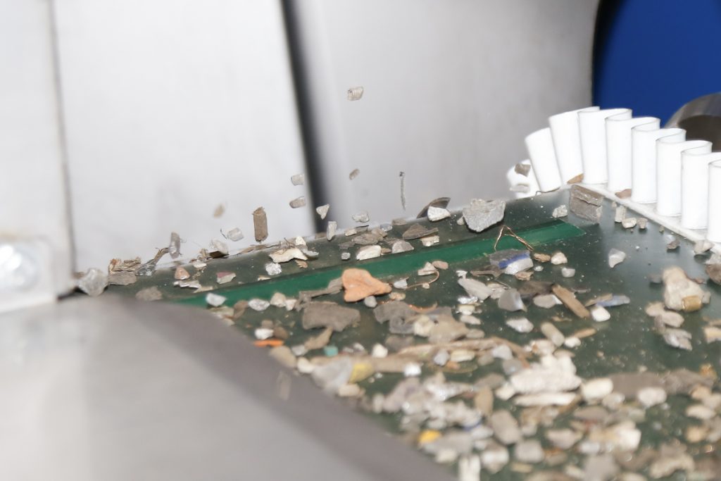
The range of Bunting Eddy Current Separators includes both concentric and eccentric rotor configurations to suit a wide range of separation objectives. The range also includes Laboratory and Pilot-Plant scale Eddy Current Separators, which are used for testing purposes at Bunting’s UK-based Centre of Excellence.
The Eddy Current Separator utilises magnetic forces to physically repel non-ferrous metals and enable a separation from non-metallic materials. The Eddy Current Separator is often supplied as part of a metal separation module along with a first-stage Drum Magnet removing ferrous metals.
- Technical product information: Eddy Current Separator
Principles of Eddy Current Separation
An eddy current separator is a dual pulley conveyor system, where the non-metallic head pulley houses an independently rotating high-speed magnetic rotor. Separation occurs when a non-ferrous metal particle (e.g. aluminium, copper or zinc) is conveyed into the magnetic zone. The non-ferrous metal particle is exposed to rapidly changing magnetic polarity. In accordance with Faraday’s Law of induction, electric currents are induced when conductors enter a rotating field (e.g. non-ferrous metals such as aluminium). By Lenz’s Law, the induced eddy currents create a magnetic field that opposes the magnetic field that created it, thus resulting in the conductor being repelled away from the magnetic source.
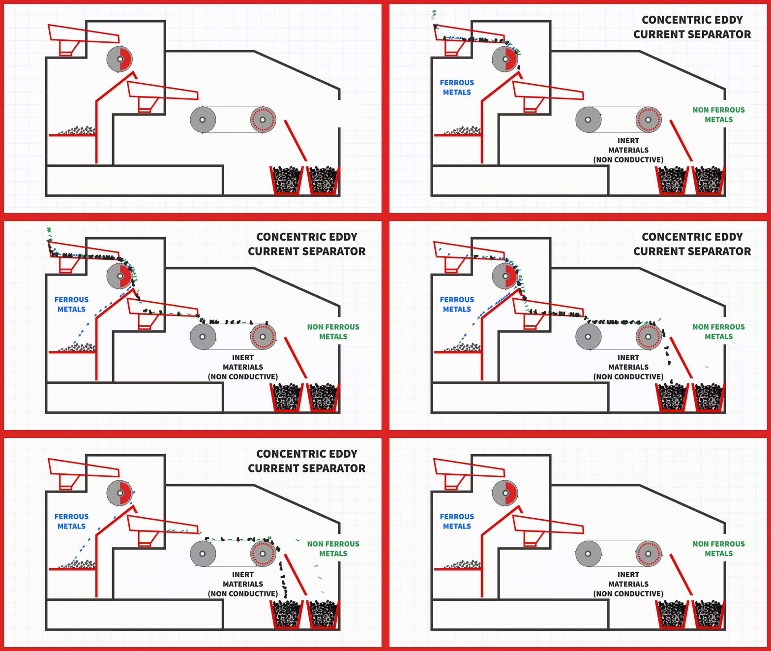
The two magnetic fields oppose against each other (i.e. North vs North pole repulsion), causing the repulsion of the non-ferrous metal particle and change in trajectory. The measured positioning of a splitter enables the separation of non-ferrous metals from non-metallic material due to the altered and unaltered material trajectories.
The speed of the magnetic rotor is dependent on the number of poles on the magnetic rotor and the application.
Operation of an Eddy Current Separator
A mix of non-magnetic material, within a governed particle size range, is fed via a conveyor or feeder onto the Eddy Current Separator belt. This runs at a higher speed than the material feed allowing the material to spread out, ideally into a mono-layer. The material is conveyed into the head-pulley separation zone, where non-ferrous metals are repelled out of the non-metallic host material. The rejected non-ferrous metals are propelled over a strategically placed splitter and onto a collection conveyor or into a bin.
Separation Variables for the Eddy Current Separator
Material Variables
For a separation to occur, the eddy current forces produced by the separator need to induce enough energy to cause a reaction. The amount of energy induced into a non-metallic metal is proportional to the metal’s conductivity, size, shape and weight/density. The ability to impart a separation is also dependent upon the characteristics of the hosting non-metallic material.
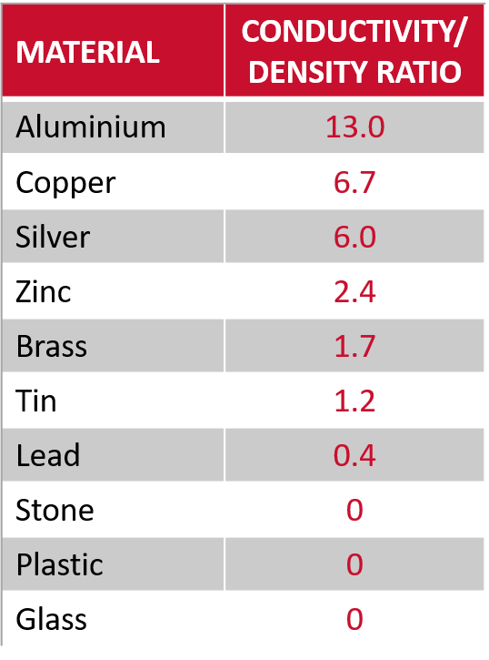
The conductivity/density ratio of non-magnetic materials (Table 1) indicates how well a particle reacts. Metals with a high ratio react well and have good separation characteristics.
In practice, the most powerful Eddy Current Separators inject enough energy into particles with a high conductivity/density ratio to produce a reaction on particles as small as 3mm. However, due to the particle size, the energy produced is low. A separation is possible if the particle size range of the hosting material is tightly controlled between 1 and 5mm. As the particle size range broadens, the ability to separate such small sized non-ferrous metals diminishes as there is not enough energy to move the particle a sufficient distance to enable a separation.
The particle shape is another separation variable determining the ability to produce a separation. Flat particles respond well, whereas spheres or wires are more difficult. This is due to the reaction within the particle. The eddy current force causes the particle to turn and then spin. Flatter particles flip and lift whilst circular particles simply turn without being repelled away from the magnetic rotor.
Eddy Current Separator Variables
Rotor Speed
To inject the maximum amount of repulsive energy into a non-ferrous metal particle there needs to be a dwell time when the two opposing fields meet. If this time is too short then not enough injected energy is generated. In operation, very high rotation speeds do not allow for sufficient dwell time to inject the necessary energy to produce a good separation.
In practice, the optimum rotational speed is unique to each design of Eddy Current Separator magnetic rotor and can vary between 2000 and 5000 RPM.
When deciding on an optimum rotational speed, there are mechanical considerations such as maintenance and wear. As the magnetic rotor speed increases, there is a higher wear factor on key components such as bearings. In operation, the ideal magnetic rotor speed is commonly set at between 2000 and 3000 RPM, balancing separation performance and wear.
Belt Speed
As Eddy Current Separators have different designs of magnetic rotor and the variety of shapes, sizes and characteristics of non-ferrous metal particles is extensive, there is no one belt speed that suits all and each time the application needs to be studied and understood to enable the best level of separation.
Feed Method
For optimum separation, the material needs to be ‘settled’ on the conveyor belt before entering the ‘separation zone’ and this is one of the reasons for a long belt.
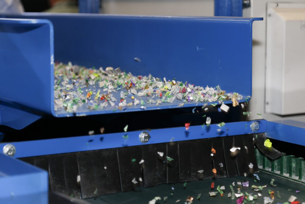
However, the best level of separation is achieved when material is fed onto the conveyor belt via a Vibratory Feeder. The Vibratory Feeder evenly spreads the material, ideally into a mono-layer, before dropping onto the conveyor belt. As the flow of the material is controlled by the vibration of the Vibratory Feeder, and the end of the feeder tray is close to the surface of the belt, the material settles down quickly and hence a shorter conveyor belt can be used.
In conclusion, the length of belt depends on how the material is being fed:
- If being fed straight from a conveyor, have a long belt;
- If being fed via a Vibratory Feeder, have a shorter belt;
Rotor Configuration
The Eddy Current Separator is a conveyor with a magnetic rotor acting as a magnetic head pulley. Due to the laws of physics, the Magnetic Rotor will attract ferrous metal and so could be used to separate magnetically susceptible materials. However, there are some limitations:
- Concentric Magnetic Rotors (i.e. the magnetic rotor spins uniformly within an outer non-magnetic shell): On Eddy Current Separators with concentric rotors, it can be difficult to discharge magnetic material from the belt. Due to the high speed rotating magnetic field, any magnetic material that is not discharged and remains vibrating at the bottom of the rotor, can get hot and, when the conveyor belt stops, can burn through the plastic of the belt and the non-metallic shell. This can then damage the magnetic rotor;
- Eccentric Magnetic Rotors (i.e. the magnetic rotor is positioned in a corner quadrant of the non-metallic shell): On designs with eccentric rotors, any magnetic material is pulled out of the magnetic field by the conveyor. This ferrous metal is discharged underneath and often into the non-metallic fraction;
However, irrespective of the rotor configuration, it is good practice to separate ferrous metals using an appropriate Magnetic Separator prior to the Eddy Current Separator. Plants achieving optimum metal recovery and separation focus on specific materials at key points in the process, including the ferrous and non-ferrous metal fractions.
Rotor Magnetic Strength
In theory, magnetic rotors with stronger magnetic fields produce better levels of separation could be true, but in practice the manufacturing and design process mean that there are limits to any magnetic rotor. All Eddy Current Magnetic Rotors are constructed from permanent magnets attached to a carrier pulley. The size of the permanent magnet (both in length around the rotor and thickness) dictates the throw of magnetic field. Longer and thicker magnets produce deeper magnetic fields than shorter and thinner magnets.
Irrespective of whether the magnet is long or short, the maximum magnetic intensity is on the pole (surface) of the magnet. Therefore, in practice, there has already been a loss of magnetic intensity by the time the field reaches the surface of the feed conveyor belt as it has passed through:
- An air gap between the shell and the magnetic rotor;
- The non-metallic shell;
- The belt;
If very short magnets are used, a very shallow and intense magnetic field is produced on the pole. However, this field may only just reach the surface of the belt. In contrast, longer magnets produce a lower field on the pole, but throw a deeper magnetic field.
This means that you could have a magnetic rotor with short and exceptionally strong Rare Earth Magnets producing a weaker magnetic field at the point of separation (i.e. on the surface of the conveyor belt) than one constructed from longer standard strength Ferrite Magnets.
Such criteria also makes it very difficult to classify any magnetic rotor as being ‘strong’ or ‘weak’ as this definition is totally dependent on where the measurement to support that description is taken. For example:
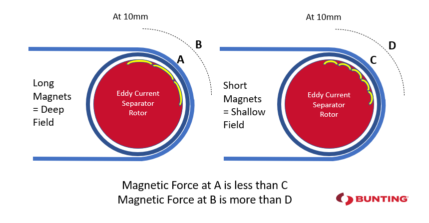
Magnetic rotor selection is dependent on the metals requiring separation. For large non-ferrous particles (e.g. aluminium can), requiring a magnetic field projected into the centre of that particle for maximum separation effect, then a deep magnetic field with longer magnets is preferable. For small non-ferrous metal particles (e.g. granulated cable), then a shallow magnetic field with shorter more powerful magnets will produce the best separation.
Applications
Eddy Current Separators are successfully used to recover and remove non-ferrous metals in a wide-range of recycling applications.
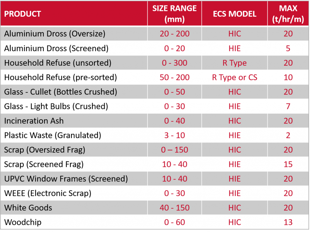
The separation performance and capacity varies according to the application and characteristics of the material (Table 2). The operating criteria for any single project are often optimised with controlled testing at the Bunting Centre of Excellence. The physics of Eddy Current Separator design limits the effective particle size that can be processed on the separator. Typically, conducting particles (even copper and aluminium) struggle to be thrown far enough as the eddy current forces and induced energy are too low, compromising metal recovery and revenue optimisation.
Eddy Current Separator Models
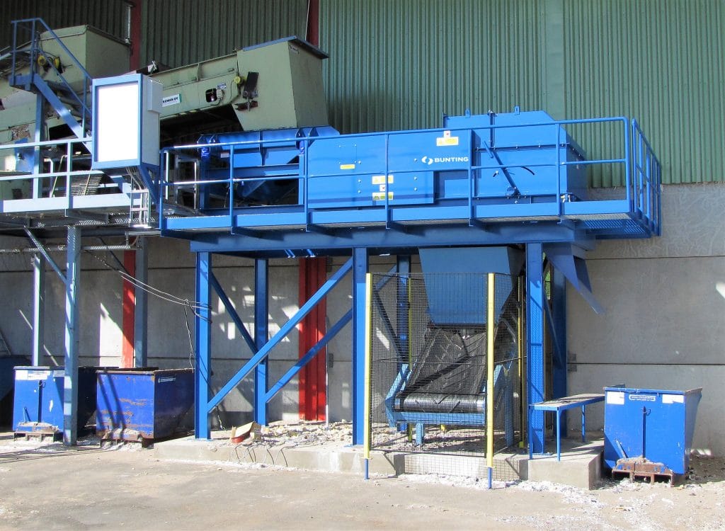
To maximise the separation and recovery of non-ferrous metals, Bunting has developed four different eddy current separator designs:
- High-Intensity Concentric (HIC) ECS – for small non-ferrous metals (50mm down to 5mm)
- High-Intensity Eccentric (HIE) ECS – for small non-ferrous metals below 10mm;
- R Type ECS – for general recycling applications where non-ferrous metals are above 20mm;
- Can Sorter (CS) ECS – A low-cost model designed specifically for the separation and recovery of aluminium beverage cans;
ElectroStatic Separation
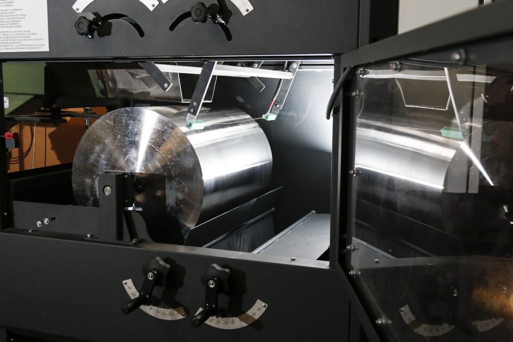
The Electrostatic Separator separates conducting from non-conducting materials in a size range of +45 microns to 4mm. The technology enables the recovery of metals commonly difficult to separate on an Eddy Current Separator and, subsequently, lost to waste.
Principles of ElectroStatic Separation
Every material has electrostatic properties that potentially allow separation in an external electrostatic field. For metal recycling applications, materials are categorised into conductors and non-conductors (dielectric) materials. When an electrostatic field is applied the particles behave differently, thus enabling a separation.
- Technical product information: ElectroStatic Separator
Conductor materials (mostly metals) will lose the charge to an earthed surface, whilst non-conductors (plastics, glass, and stone) will retain the charge and be pinned to the earthed surface. This effect is known as ‘image charge’ and is the operating principle of the ElectroStatic Separator. This effect can be utilised to separate highly conductive metals from lower conductivity metals (e.g. aluminium from copper) or conductors from non- conductors (granulated copper cable from plastic insulation).
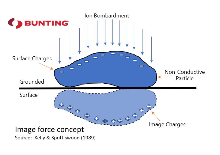
ElectroStatic Separation exploits the difference in electrical conductivity between various materials in a feed material to produce a separation. The ability to produce a separation depends on a number of key material characteristics including conductivity, moisture content and size range. In many applications, often due to the fine particle size, the ElectroStatic Separator is the only technology that enables a separation. The technology also replaces less environmentally-friendly separation processes such as froth flotation.
The technology is used to either attract or repel particles, both enabling a separation. When using attractive forces, conducting particles stick to an oppositely charged object, such as a metal drum, thereby separating them from other particles. When the type of beneficiation uses repelling force, it is normally employed to change the trajectory of falling objects to sort them into different fractions.
There are three main methods of particle charging/electrification.
- Charging by ion bombardment (corona charging);
- Charging by induction;
- Tribo-charging (frictional charging)
The Bunting ElectroStatic Separator uses Corona charging to generate an electrostatic field as this is the most efficient method for metal recycling and mineral processing applications at tonnes per hour capacities.
Operation of an ElectroStatic Separator
Feed material (e.g. granulated copper cable) is fed via a controllable vibratory feeder onto the revolving earthed roll in a monolayer. A voltage is applied to the static electrode (typically 20-30 KeV) which generates an electrostatic field as the particles fall onto the roll. Conducting particles (e.g. copper) instantly lose their charge to the earthed roll and are throw off by the imparted centrifugal force generated by the revolving roll. Insulating particles (e.g. plastic) will keep their charge and create an image force that pins it to the roll.
If the image force is greater that the potential centrifugal force generated by the revolving roll the particle will remain pinned to the roll and is discharged by a brush into a separate chute.
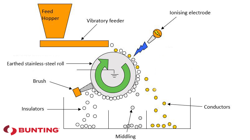
Hence a separation takes place on a continuous basis at tonnes per hour capacity for free flowing materials.
Separation Variables
The processing history of a sample dictates the ElectroStatic Separator settings. Controlled laboratory tests at Bunting’s Centre of Excellence identify the key parameters needed to optimise and then meet the separation objective. The key control variables for separation are:
Material Variables
Particle size range
The ElectroStatic Separator works effectively with a particle size range of between plus 45 micron and minus 4mm. Therefore, this technology enables processors to recycle fine particle size fractions that cannot be effectively treated on an Eddy Current Separator.
As with all physical separation processes, closer particle size range distribution increases separation efficiency. This enables the roll speed and splitter plate positions to be optimised with greater precision, thereby increasing grade and recovery of material being processed.
As with any physical separation, processing excess fine material (under 45 microns) can inhibit the separation efficiency and cause flow issues on the feeding process. Inclusion of this fraction also compromises feed capacity, as a consistent monolayer of material is needed to achieve optimum grade and recovery of valuable metals.
Low moisture content of the feed
Surface moisture inhibits the separation efficiency of the unit meaning that the feed must in a relatively dry state and free flowing.
ElectroStatic Separator Variables
Applied voltage
For most recycling applications an applied voltage of 20-30 KeV to the tungsten electrode is sufficient. Separation control is achieved by changing the applied voltage in this range to change the quantity of insulator material that is pinned; subsequently adjusting the grade and recovery of the material. The higher the applied voltage- the greater the image force and the more material is pinned. This is particularly useful where there is a proportion of none liberated metal/ plastic scrap material.
Roll speed
The rotational speed (i.e. the centrifugal force) of the roll throws the conducting material (copper/aluminium) from the earthed roll. Balancing the applied voltage, which pins the insulators (plastics), and the roll speed, allows for the creation of separate streams of materials for continuous separation.
Splitter plate position
Adjustable splitter plates enable the separation of the conducting/non conducting fractions. In some applications, an additional splitter produces a third ‘middlings’ fraction of non-liberated material, which is often returned to an earlier point of the process for further granulation or shredding to improve liberation.
Low humidity atmospheric conditions (hence units have heaters)
Surface moisture adversely affects some more sensitive separation and, therefore, the Bunting ElectroStatic Separator has an optional heating unit to control the relative humidity.
Electrode position
The position of the tungsten electrode is adjustable to optimise sensitive separations between materials with similar conductivity.
Applications
ElectroStatics is a long-standing separation technology in the minerals industry dating back to the late 1890s. However, the necessity of recovering or separating smaller metal particles from waste products has resulted in many companies investing in ElectroStatic Separations. Typical applications include:
- Secondary metal recycling (Table 4):
- Recovery of Platinum Group Metals from waste
- Granulated Copper Cable Processing
- Separation of Aluminium from Plastic
- Separation of copper from mixed copper /aluminium product
- Mineral processing (e.g. used in conjunction with high-intensity magnetic separators in separating beach sands);
- Plastic recycling (e.g. shredded window frames separating aluminium from plastic);
- Shredded WEEE/Auto Shredder Residue
- Food separations (e.g. Tea processing).
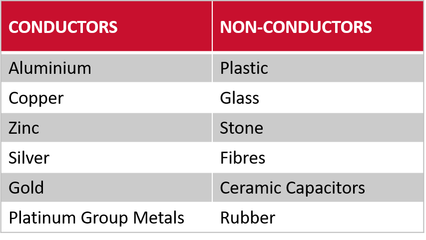
Capacities per meter width for metal recycling applications are commonly 2-3 tonnes per hour, although any capacity and separation are both dependent upon the material characteristics. Such performance criteria are proven with controlled tests at the Bunting Centre of Excellence.
- Related technical articles: ElectroStatic Separation of Minerals
Summary
Technology holds the key to increasing the proportion of waste materials reclaimed, reused and recycled. Used in combination, and alongside magnetic separators, the Eddy Current Separator and ElectroStatic Separator enable the recovery of a high proportion of the metallic (ferrous and non-ferrous) materials from any waste.
In practice, the Eddy Current Separator is ideally suited for recovering or separating non-ferrous metals above 3mm. ElectroStatic Separators are perfectly suited for the smaller fraction, separating and recovering conductive metals from 4mm down to +45 microns. ElectroStatic Separators also have the ability to separator different conductors, such as copper from aluminium on tightly-sized fractions.
For additional information on Eddy Current Separation or ElectroStatic Separation, including tests at Bunting’s UK Centre of Excellence, please contact us on:
Email: Gordon Kerr at GKerr@buntingmagnetics.com
Telephone: +44 (0) 1527 65858
Follow us on social media