Magnetic Separators For Mineral Processing
By Paul Fears | 22 October 2018
Magnetic separators can be found in most mineral processing operations, especially those processing non-metallic minerals and magnetic ores. This article investigates the use of high intensity magnetic separators and magnetic separation equipment in the minerals sector with a focus on processing dry materials (in the -15mm, +45 micron size range).
Principles of Magnetic Separators
There are three magnetic properties of minerals. Each type enables separation using industrial magnetic equipment and are:
- Paramagnetic: Minerals that are only slightly affected by an applied magnetic field. They move towards concentration in lines of magnetic flux (e.g. hematite, ilmenite, and chromite).
- Ferromagnetism: Minerals capable of achieving a high degree of magnetic alignment (e.g. magnetite).
- Diamagnetism: A mineral (e.g. silica) that is very weakly repelled by the pole of a strong magnet. When a magnetic field is applied, a diamagnetic mineral will develop a magnetic moment through induction but in the opposite direction and is therefore repelled.
The magnetic separation of minerals is based on a three-way competition between:
- Magnetic forces;
- Gravitational or inertial forces;
- Inter-particle attractive and repulsive forces;
The combination of these forces determines the outcome of any given magnetic separation and is much affected by the nature of the feed such as size distribution, magnetic susceptibility and other physical and chemical characteristics.
Control Variables
The control variables to optimise separation efficiency can be summarised as follows:
Feed Variables
- Volume of Particle (V) (function of feed particle size distribution).
- Magnetic Susceptibility of Particle (K) (a function of the mineral type and liberation).
Machine Operation Variables
- Magnetic Field Strength of Separator (H) (Machine Design Parameter)
- Magnetic Field Gradient of Separator (H/R) (Machine Design Parameter)
The magnetic force F(m) generated on a paramagnetic particle in a magnetic separator is given by:
F(m) = V.K.H.H/R
For a successful separation, the magnetic force F(m) must be able to move the paramagnetic mineral from its natural path immediately after leaving a separator, or lift it from a belt (overcoming gravity) in the case of a Disc type magnetic separator.
Magnetic Separator Designs
These principles are used in the design and application of 3 types of magnetic separation equipment used for the dry processing of mineral deposits.
Rare Earth Roll Magnetic Separator
The Rare Earth Roll Magnetic Separator uses Neodymium Iron Boron permanent magnets (the most powerful permanent magnets available) built into a composite high-intensity magnetic head pulley. High separation efficiencies are generated by:
- The design of the magnetic roll assembly (using high grade neodymium magnets);
- The optimum pole spacing to generate high magnetic field strengths and magnetic field gradients;
- The optimum combination maximises the magnetic force exerted on a paramagnetic particle as it passes over the roll;
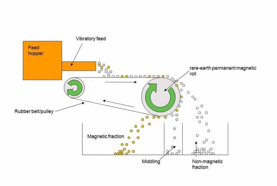
Non-magnetic material is discharged forward of the roll, in a natural trajectory. Any magnetic particles are influenced by the roll’s magnetic force and are discharged on the underside of the roll into a separate chute. Separation trajectories are set by adjusting the conveyor speed using an inverter control and adjusting the splitter chutes. The captured material can be captured in 3 collection areas or chutes:
- Non-magnetic;
- Middlings (weakly or paramagnetic minerals);
- Magnetics (ferromagnetic minerals);
Magnetic rolls are available in 75mm, 150mm and 200mm diameters, up to a width of 1 metre. Multiple configurations of rolls are available, giving the non-magnetic fraction a further pass for improved product purity or recovery. The Rare Earth Roll Magnetic Separator can process a wide size range of material ranging from 75 microns up to 15mm. Although, as with all physical separation processes, a tight control of the particle size range improves separation efficiency.
Typical magnetic separation equipment applications include the removal of iron mineral contamination from silica sands, feldspar and other non-metallic industrial minerals. Rare Earth Roll Magnetic Separators are also used when processing granulated slag, upgrading ilmenite, processing beach sands, and in recycling applications such as removing fine iron from cullet (crushed glass). Typical capacities range from 2-4 tph per metre width, but are dependent on the material characteristics and separation objectives.
- Technical Product Information with Video: Rare Earth Roll Magnetic Separator
Key Facts about the Rare Earth Roll Magnetic Separator
- Large particle size range processed (15mm-75 micron);
- Magnetic Roll design gives high magnetic flux gradient hence high separation efficiency;
- Three Magnetic Roll diameters available;
- Low operating costs;
- Small machine footprint;
- Simple to install and operate;
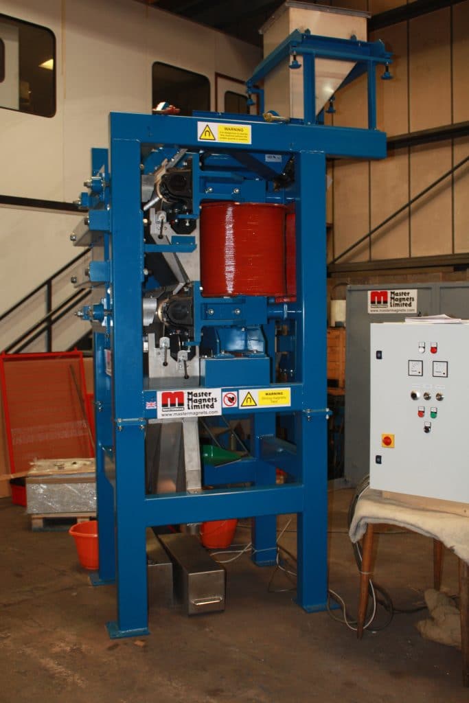
Induced Magnetic Roll Magnetic Separator (IMR)
The Induced Magnetic Roll Separator (IMR) is used for the continuous extraction of small paramagnetic particles. The IMR is used for mineral purification in a wide range of applications in the mineral and ceramic processing industries.
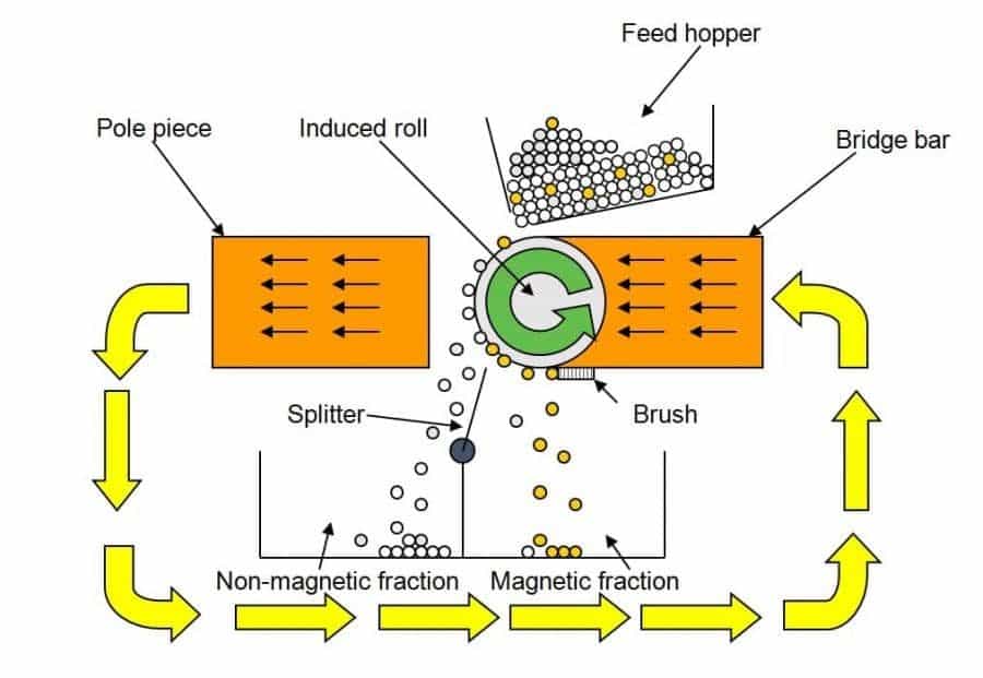
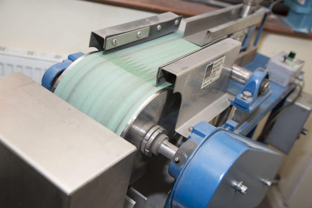
The high magnetic field in an Induced Roll Magnetic Separator is created through electromagnetism. In operation, material is fed from a hopper or vibratory feeder at a controlled rate onto the high intensity magnetic roll. Paramagnetic material is attracted onto the roll face or is deflected towards the roll. Non-magnetic material is discharged from the face at a normal trajectory. Captured magnetic material is discharged off the roll face at a point of lower magnetic intensity, aided by a brush.
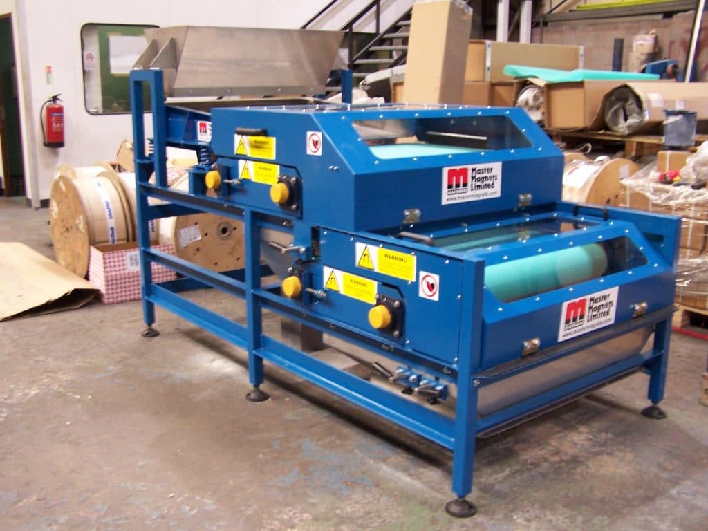
A splitter plate is positioned between the two product streams. In addition, a second splitter plate can be added to the IMR to produce a middlings stream. As with the Rare Earth Roll Magnetic Separator, two rolls can be mounted in series on the same unit to give a double pass machine for improved efficiency and process performance.
This type of Magnetic Separator provides great flexibility for the process engineer. The magnetic field strength is variable due to the adjustable electro-magnetic coil. Also, the roll speed is adjustable and the roll/pole gap can be adjusted to accommodate different feed size ranges. The IMR can also process hot mineral feeds (up to 80-100 C) without compromising separation efficiency, unlike the permanent magnetic Rare Earth Roll Magnetic Separator equivalent.
As the magnetic roll generates very little static charge on the surface, there is a minimal carryover of fine particles into the magnetics fraction. Thus producing good grades and recoveries of valuable minerals. Typical capacities for a metre wide unit vary based on mineral type, density and particle size distribution and are ideally determined by laboratory test trials. Installation experience has shown that the following capacities are a good guide:
- Concentration of ilmenite sands: 4tph;
- Chromite concentration: 3-5tph;
- Silica sand upgrading: 2-3tph
Key Facts About the Induced Roll Separator
- Separates weakly paramagnetic minerals from non-magnetics;
- Roll and Pole gaps are variable;
- Capable of processing minerals in the -2mm, +45 micron particle size range;
- Roll speed is variable (typically 80-120 rpm);
- Splitter plate position variable;
- High Magnetic Field Strength up to 2.2 Tesla (22,000 Gauss);
- Flexible Feed configuration;
- Machine design gives low carryover of fines into magnetics fraction;
- Remove ferromagnetic material (grinding iron or magnetite) from feed prior to processing.
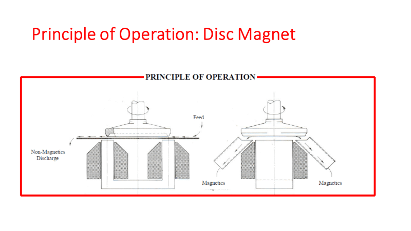
Magnetic Disc Separator (MDS)
Original designs of the Magnetic Disc Separator date back to the early 1900s. Although manufacturing techniques have significantly changed and more advanced machines have now been incorporated, the basic design still remains virtually the same.
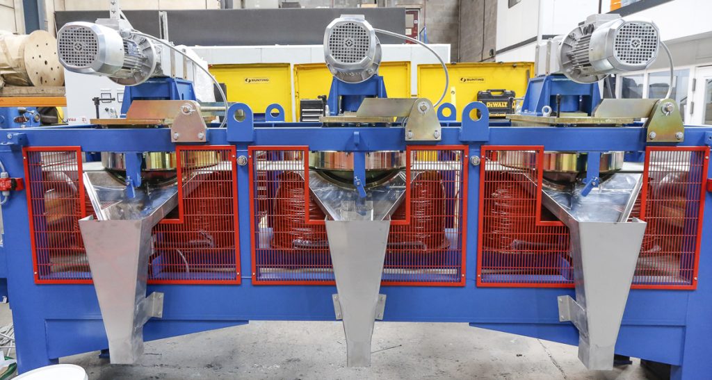
Typically, a Magnetic Disc Separator will feature up to three high-intensity electromagnetic discs, each set at a different height from a feed conveyor. The first disc will be set the furthest from the feed material, in order to extract only the most magnetically susceptible particles. The second and third discs are set at lower gaps, increasing the magnetic force at each disc and therefore separating different grades of magnetic material. Magnetic intensity can also be further adjusted by varying the current of each coil to suit each client’s specific mineral separation requirements.
Feed material is discharged from a hopper onto a vibratory feeder tray. A mono layer of material is continuously fed between the rotating high-intensity magnetic discs, where magnetic particles are attracted to the high-gradient zones on the discs. These captured particles are then carried by the rotating discs to the discharge chutes where they are released. Scrapers that are mounted on each of the chutes ensure the total discharge of the extracted magnetic particles. Any feed material that is non-magnetic will pass under each of the three discs and discharge at the end of the conveyor.
Typical applications for the Magnetic Disc Separator include the removal of weakly magnetic minerals from high quality quartz sand, processing of ilmenite beach sands, monazite/zircon separation, garnet concentration and wolframite/cassiterite separation. One of the most common applications in recent years is processing columbite (used in mobile phones) and tantalite (used for glasses and cameras) on the African continent.
Key process advantages of these units include a high magnetic field strength and gradient with variable magnetic field control at each the edge of disc (giving 6 different magnetic fractions). This gives highly selective mineral separations. It also offers flexible processing for complex mineral mixtures (e.g. rutile, zircon ilmenite, monazite, garnet, silica). The Disc Magnetic Separator also has variable disc rotation speed and belt speed optimum separation efficiency.
Key Facts About the Magnetic Disc Separator
- Design permits smaller air gap between mineral and disc hence greater selectivity for mineral separation;
- Series of adjustable discs (incorporating groves for field gradient concentration) revolving around a conveyor belt;
- Typical field strengths can be varied between 1000 Gauss to 14,000 Gauss. (1.4 Tesla);
- A range of belt widths are available;
Related Mineral Processing Technical Article
Magnetic Separators – Mineral Processing Laboratory
Bunting-Redditch has one of the most comprehensive magnetic separation mineral processing testing laboratories in the world. Their Laboratory Technicians have decades of experience in mineral processing. Controlled tests ensure that the most suitable and cost-effective machinery is recommended for each application.
The laboratory is equipment with a wide range of equipment including:
- Smaller scaled versions of industrial Magnetic Separators. This equipment is used to accurately scale up to industrial capacities and calculate performance guarantees;
- X-Ray Fluorescence and X-Ray Diffraction analysis are available for chemical assay and mineralogical identification to aid the development of a viable process route for each application;
For further information on our range of magnetic separation equipment designed for purifying ceramics and non-metallic minerals, or to arrange sample tests in our laboratory, please contact us on:
Email: Gordon Kerr at GKerr@buntingmagnetics.com
Telephone: +44 (0) 1527 65858
To keep up to date with our news and technical reports, please follow us on social media